Laser Projector
Introduction
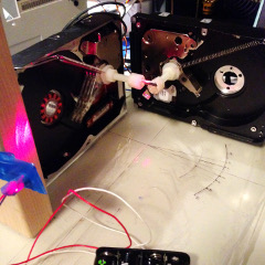
As a project for an Embedded Systems course, our group (Doan, Tyler, Jeff, Taylor, and myself) decided to build a simple laser projector. Our primary constraints were time and cost. We had less than four weeks to design and build a laser projector from the ground up, and we wanted to to be inexpensive. Consequently, we designed an open-loop design using hard drive voice coils as actuators, controlled by an Arduino Nano. By mounting two hard drives at right angles and mounting small mirrors to each hard drive, we created a simple two-axis galvanometer system, allowing for extremely rapid movement of the laser.
Electronics
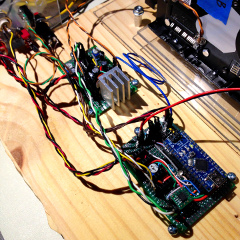
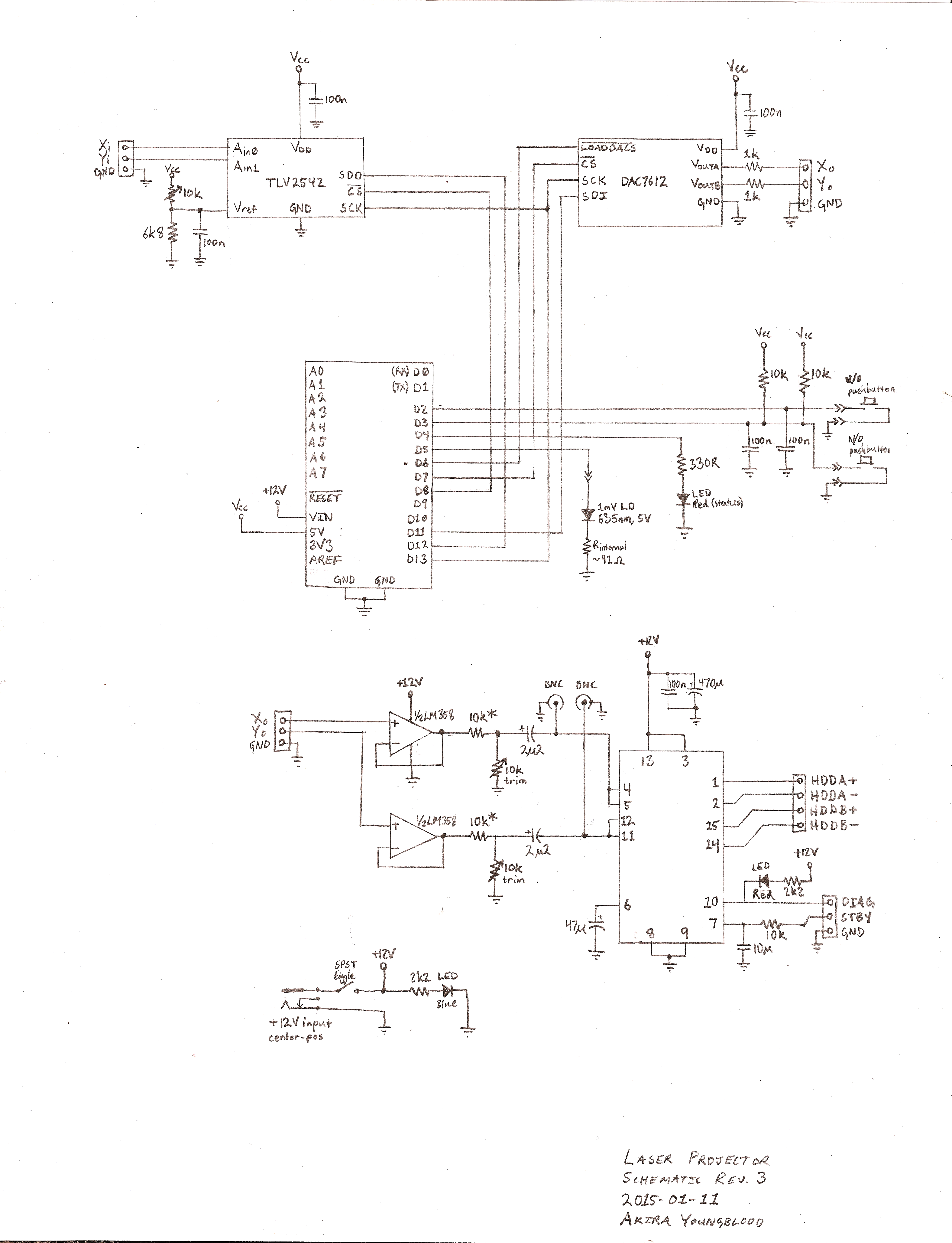
The Arduino Nano continously updates a dual, 12-bit DAC (we used a Burr-Brown DAC7612) via SPI. As the mechanical bandwidth of the galvanometers is less than 1kHz, the chosen DAC gives us a more than comfortable margin in both precision and sample rate. We use a 20W audio amplifer, an STA540, to drive the galvanometers. We chose the STA540 because it can be powered from a single supply and the BTL design eliminates the need for DC blocking capacitors. Given the DAC output range of 0-4.096V, the supply voltage of 12V, and the STA540's fixed gain of 20dB, we need an intermediate gain/offset stage between the DAC. We use an LM358 to buffer the signal, then divide it by four and remove the DC component. This leaves us with a bipolar signal that has more than enough range to drive the galvanometers to their limits. In the future, this attenuation will be increased so as to reclaim some of the DACs range for enhanced accuracy. The power amplifier drives the voice coils directly, as hard drive voice coils are remarkably similar to speaker voice coils.
User input is a simple toggle switch and button located on a side panel. The panel also has connections for audio input (yet to be implemented in software), as well as BNC test points for verification of the output signal or override of the DAC. Additionally, the main circuit board has sockets for two ADC chips, allowing future addition of analog feedback for a closed-loop design and audio input.
Finally, the laser diode itself is driven directly from an Arduino I/O pin. We used a 5mW 635nm (red) laser diode with a built-in current-limiting resistor. As the diode only draws 20mA, no driver circuitry is required, greatly simplifying the overall design. Consequently, we can toggle the laser very quickly, allowing for a number of interesting visual effects.
Hardware
The mirrors are cut from hard drive platters, which are an incredibly convenient source of front-surface mirrors (front-surface mirrors are necessary for laser manipulation). We mounted the mirrors on the voice coils using nylon bolts, chosen for their low mass and easy machinability. To prepare each hard drive for use as galvanometers, we simply removed the platters, and added springs to return both galvanometers to center. The hard drives are mounted directly to a sheet of Plexiglas, using the original mounting holes. The laser is elevated using a small piece of maple. The entire sheet of Plexiglas is mounted to a wooden board, which holds the circuit boards and other components.
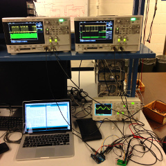
Through experimentation, we determined that the mechanical bandwidth of this system was quite limited, but still enough to draw a variety of shapes. The mirrors begin to lose repeatibility below 20Hz, and deflection is severely attenuated above 300Hz. Therefore, we only have about an octave of bandwidth in which to play in, which rules out sharp corners in the shapes draw. Reducing the mass of the actuators would greatly improve the response of the system. In the future, we plan to alter the armatures to reduce mass and improve the focus of the laser, which should greatly improve the clarity and high-frequency response.
Software
The software is very simple. We store a few wavetables as a starting point for the X and Y signals. The code runs a tight loop that continously calculates new values by iterating though the wavetables and applying simple arithmetic, then updates the DACs. Through some careful programming, this loop is quite performant, and easily keeps up with the desired output frequency of 50-150Hz (we found that the galvanometers responded best to this range). This loop also modifies the blanking of the laser to create more complex patterns. There are a number of different patterns programmed, and switches allow the user to cycle through these patterns. In the future, we plan to add code to support audio input, selectable via the same switches.
Media & Resources
A photo gallery of the project is here. Videos coming soon; recording video of the projected patterns is difficult due to the nature of CMOS sensors.
The hand-drawn schematic can be viewed here (PNG, 5MB). A revised schematic and BOM are coming soon.